some special expressions in cases of GG1s and PRR in alphabet order:
Why is she called the GG1?
The Pennsylvania Railroad had a standard system for identifying locomotives by wheel arrangement. For example a 4-6-2 was a K, a 2-10-0 was an I, a 2-8-2 was a L. subsequent models would get a number such as K2, K3, K4. Of importance here, is a 4-6-0 was a G. When articulated locomotives were introduced, either electric or steam, it was classified as two locmotives back to back. The GG1 is a 2-C+C-2 in Diesel terms, but a 4-6-0+0-6-4 in steams terms, so it was two G lomotovies back to back, hence GG. First revision makes it the GG1 (there was no GG2, but all electrics got a trailing number, although all steamers did not.)
Brunswick Green
Officially listed as PRR dark green locomotive shade and is sometimes defined as 8 parts black and 1 part green.
Carbody
Another name for the shell or skin of the GG1
Catenary
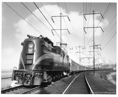 A GG1 with "Congressional Express"
 The supporting wires and structures to carry the overhead current conducting wire from which electric locomotives obtain power.
Cat Whiskers
The pin stripes on the GG1
Double Pantograph Order
On icy days or during sleet conditions both pantographs were ordered to be up. With both pantographs up the leading one would act as a scrapper to insure that the trailing one would make good contact with the overhead wire.
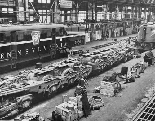
Frame

GG1's frames and bogies in maintanance shop in Wilmington, DE
Foundation or chassis upon which a locomotive is built.
Front
The half of the GG1 that contained the steam boiler was designated the "front" or end #1 the other half was designated end #2. Most GG1's had an "F" on the carboby to indicate the front end. Messenger Wire - The graceful shaped wire that carries the trolley wire.
Motor
A descriptive term used on the PRR to mean electric locomotive.
Multiple Unit
Two or more locomotives coupled together under the control of one engineer. Controls on the individual locomotives are interconnected via electric cables (MU cables) or hoses so they act in concert with the single control.
Overhead
Catenary and contact wire of a suspended electrical distribution system.
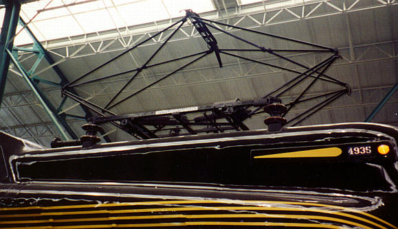
Pantograph
A device mounted on the roof of an electric locomotive that is spring loaded to allow the pick-up shoe to maintain contact with the overhead trolley wire.
The pantograph is a diamond - shapped device mounted on the roof of the GG1 (and other electric locomotives) to permit current from the overhead 11,000 Volt AC cantenary contact wire to be collected to feed the traction motors.
The height of the overhead conductor ranges from a minimum of 16' - 10" to a maximum of 25' - 0" and the pantograph is hinged and spring loaded to permit it to colapse and expand to compansate for the variations in height and to allow its pick-up shoe to maintain good contact with the conductor.
 diagram of PRR-panthograph
 The diamond - shapped framework consists of four movable sections of tubular steel members hinged together and secured to two length of angle iron. The framework consists of four movable sections, two upper and two lower. The two upper sections are hinged together at the top and hinged to the lower sections which in turn are fastened through hinges to the length of angle iron. Each section is assembled from high carbon steel tubing and cast fittings to form a rectangle with diagonal cross bracing through an "X" shapped center fitting The entire assembly is mounted on four insulators. The insulators are made up of two porcelain petticoats placed one on top of the other and cemented to a vetical pin fastened to a wide steel plate that is bolted to the roof. The angle iron bases are bolted to a steel cap placed on top of the insulators.
The contact shoe is made up of flat steel 4" wide and 1/2" thick and it is mounted just above the top hinges. Downward curving horns are fitted at each side of the shoe to prevent snagging of the contact wire at crossovers.

a GG1-phantoghraph on PRR#4935 in Strasburg, PA
The pantograph can be lowered by air pressure and when it is lowered it is held down by a latch which catches a crossmember of the upper framework. The latch can be unlocked by air pressure and when the latch is released the pantograph is raised by the springs.
The GG1 was equipped with two pantograph, but only one needed to be raised to operate the locomotive, because they were jumpered together and connected to the on board transformer through a common current path. The usual practice was to operate with the forward pantograph in the locked down position and with the rear one raised. This practice was adopted because if the raised rear pantograph was struck or came apart the one in front could be used, but if the one in front was raised and it fell apart it could render the rear one inoperable.
Quill Drive
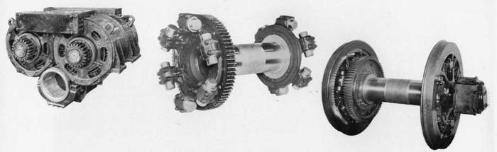
Traction motors are mounted on a hollow tubes called a quills. The quills are concentric to the driving axles and connected to large gears which in turn are connected to the driving wheels. The gears are turned by pinions mounted on the motor shafts. The GG1 used two traction motors per axle with each motor having a saft and pinion on each end. motor sets, cardan and driving axle
The Quill Shaft Assembly was a critical component in the GG-1's traction-motor/drive wheel system, in that its function was to transmit power from the motors to the drive wheels.
The GG-1 Class locomotive had 12 traction motors, which powered the engine's six drive axles. These motors were rated at 385 HP each, thus providing 770 HP per axle for an engine total of 4620 HP. The traction motors, assembled in pairs, were single-ended, with each having a drive pinion mounted on one end of an armature shaft. Each pair of motors was connected to the driving wheels through the quill shaft assembly. This assembly was supported in a pair of journal bearings located beneath the two motors. In turn, these bearings were mounted in a housing that was integral to the motor-drive assembly.
The quill shaft was essentially a hollow tube that surrounded the drive axle. Mounted on one end of the quill shaft was a large bull gear which meshed with, and was driven by the pinions on the traction motors. Also mounted on each end of the quill shaft was a "spider-drive" assembly, on each of which were mounted six "drive-cup" assemblies. It was through the contact of these "drive-cups" with the radial spokes of the drive wheels, that power from the traction motors was finally delivered to the drive wheels. This arrangement of delivering the traction power of the motors to the drive wheel through the "drive-cups" allowed the driving wheels and axle to move in reaction to track conditions without affecting the meshing of the drive pinions and the bull gear.

driving axle

a motor-set, which is sitting on one driving axleThis is the quill drive assembly which includes the bull gear and the spring and cup assemblies which engage the diving wheels and absorbed the motor thrust and torque. The quill drive assembly is mounted under the traction motors and rides in the quill bearing in the traction motor assembly.
Quill drive assembly engaged with the driving wheels. The wheel axle turns independently inside the hollow quill shaft. The driving wheels and axle can move in reaction to track conditions without affecting the meshing of the pinions and gears.
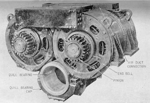
The twin traction motor assembly showing the pinion gears on each of the motor shafts. These pinions engage with the bull gear. Also notice the bearing at the bottom of the assembly in which the quill shaft rotates. 
Notice in the photo of the Frame and Driving Wheels below that the placement of the driving wheel assembly was not symmetrical. The first two sets had the pinions and bull gear located on the right side and the other four sets of pinions and bull gears were located on the left side. This asymmetrical arrangement was necessary due to the placement of other equipment in the locomotive.
Sand Box
A receptacle on a locomotive for storing sand that is pneumatically delivered through piping to the rails directly in front of the driving wheels. The sand provides increased grip for the wheels to prevent slipping.Steam BoilerSteam producing unit consisting of a fire box surrounded by a water space to produce steam for heating passenger cars.
Toluidine Red

Red color used on PRR keystones.
Traction Motor
The electric motor geared to the axles and used to convert the transformer output to mechanical force in the form of tractive effort.
Tractive Effort
The measurement of the force exerted by a locomotive at the point where the wheel tread meets the rail.
Trolley Wire
The current conducting wire that the shoe on the pantograph rubs to transmit power to the locomotive.
Tuscan Red
The brownish red color of many PRR freight and passenger cars. The color that 10 GG1's were painted in the early 1950's.
Wheel Arrangement
The GG1 wheel arrangement would be indicated as 4-6-6-4 in steam locomotive terms. On the PRR, the 4-6-0 wasa 2-C+C-2. designated as Class G. A GG1 is two 4-6-0's back-to-back, thus the "GG" and the one indicates the first design. Electric locomotives are classified by their motored and unmotored axels. The GG1 is indicated as The + sign indicates an articulated arrangement, the "C" means three powered axles and "2" means two unpowered axles.
Sources:
http://www.steamlocomotive.com/
http://www.spikesys.com/GG1/
Pictrures from (and links):
http://www.steamlocomotive.com
http://www.spikesys.com/GG1/


 1935 PRR:
 1937 PRR:
 1941 PRR:
 1952 PRR:
 1955 PRR:
 1955 PRR:
 1955 PRR:
 1968 PC:
 1968 PC:
 1968 PC:
 1969 PC:
 ca. 1970 PC:
 1976 Conrail:
 1976 Conrail:
 1976 Conrail:
 ca. 1978 Conrail:
 1971 Amtrak:
 1971 Amtrak:
 ?? Amtrak:
 ca. 1975 Amtrak:
 1981 NJT:
 1981 NJT: